introduction
Air handling units (AHUs), Air Conditioning systems (AC), fans and their parts, process plant ducts, mine tunnel ventilation, and auxiliary ventilation system components, are just a few of the HVAC industry’s many design and optimisation applications that use CFD. Engineers can now anticipate pressure drop along ducts, heating load calculations, and heat transfer rate at a very early stage of the design process thanks to the CFD technique, enabling them to create cost-effective and efficient solutions with shorter lead times for a variety of evolving demands.
Our knowledge in these subjects could help you with
- Duct optimisation
- Industrial fans performance assessment and optimisation
- Air flow distribution within buildings
- Thermal comfort of the room’s occupants
Passenger Car Thermal Comfort Analysis
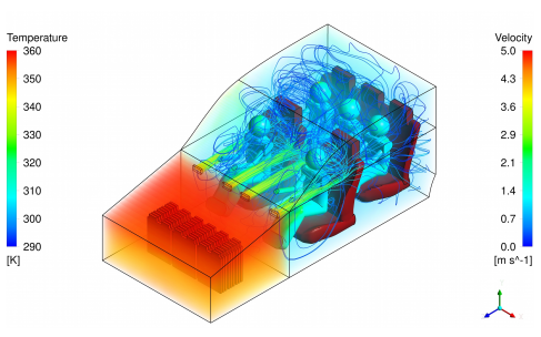
Thermal comfort is a crucial aspect of passenger car design, as it can have a significant impact on the driving experience and the overall satisfaction of the occupants. Computational Fluid Dynamics (CFD) is a powerful tool for analyzing and optimizing thermal comfort in passenger cars.
CFD simulations can be used to analyze the temperature distribution and air flow within the passenger compartment, as well as the interaction between the occupants, the air flow, and the thermal environment. This information can be used to optimise the design and placement of HVAC (Heating, Ventilation, and Air Conditioning) systems, as well as the selection of materials and insulation, to achieve optimal thermal comfort and energy efficiency.

Passenger Bus Thermal Comfort Analysis
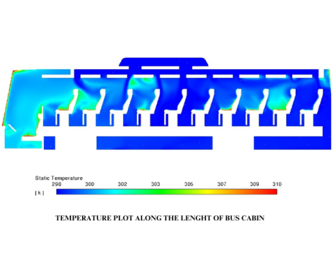
Passenger comfort is an important consideration in the design and operation of passenger buses. One of the key factors in passenger comfort is thermal comfort, which is the balance between the heat generated by passengers and the cooling provided by the air conditioning system.
CFD (Computational Fluid Dynamics) is a valuable tool in the thermal comfort analysis of passenger buses. It allows engineers to simulate and analyze the air flow, temperature distribution, and heat transfer within the bus to optimise passenger comfort and energy efficiency.
The CFD analysis begins with the creation of a 3D model of the bus interior, including the seats, windows, doors, and air conditioning system. The model is then used to simulate the air flow and temperature distribution within the bus, taking into account factors such as the number of passengers, the outside temperature, and the speed of the bus.
The CFD analysis can provide information on the temperature and air velocity distribution within the bus, as well as the thermal comfort of individual passengers. This information can be used to optimise the design and operation of the air conditioning system to achieve maximum passenger comfort and energy efficiency.


